
More Than Just Numbers: Why Mastering CFM & PSI is Key to System Design
Compressed air system design isn’t just about horsepower. It is a finely tuned balance between force and flow. Design engineers and plant managers tasked with building today’s production floors must understand how CFM and PSI work together and how their relationship affects performance. Get the balance correct, and you can enjoy maximum efficiency. Get the balance wrong, and you are likely to be faced with malfunctioning tools, excessive energy costs, and a self-defeating system.
This article doesn’t simply define CFM and PSI; we take a closer look at how they work together to determine system performance, efficiency, and profitability.
Understanding the Pillars of Performance: Flow vs. Force
Two of the most critical factors for any compressed air system are the amount of air it provides and the pressure with which it gives it. They are, of course, connected, but they are also two very separate and essential features of your compressor’s performance.
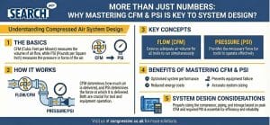
What is PSI (Pressure)? The “Force” 💪
PSI, or Pounds per Square Inch, measures pressure. Think of it as the strength or “punch” your compressed air delivers. Every pneumatic tool, from an impact wrench to a sophisticated actuator, is engineered with a minimum PSI rating required to function correctly. Most industrial tools operate optimally around 90–100 PSI (6.2 to 6.9 bar). It’s a measure of intensity. For instance, the difference between single-stage and two-stage compressors often comes down to their maximum pressure capabilities, with two-stage models reaching higher PSI for more demanding tasks.
What is CFM (Airflow)? The “Endurance” 💨
CFM, or Cubic Feet per Minute, measures the volume of air a compressor delivers over time at a specific pressure. If PSI is the strength, CFM is the system’s endurance or “lung capacity.” It determines how many tools you can run simultaneously and whether you can sustain continuous operations without a performance drop.
- Low CFM Tools: Equipment used in short, intermittent bursts, like a nail gun, requires a low CFM.
- High CFM Tools: “Air-hungry” equipment, such as sanders, grinders, or automated machinery, that runs constantly demands a much higher and more consistent CFM.
CFM and PSI work together to determine how much air your system delivers and how well your tools perform
The Critical Connection: An Unbreakable Relationship
PSI and CFM are not independent. They are inversely related, and it’s a simple principle called Boyle’s Law: the higher the pressure (PSI) you put on a gas, the less space (CFM) it has to move around. The objective measure of a compressor’s ability is always stated as its CFM at a given pressure (PSI), such as 125 CFM @ 100 PSI.
To visualize this, picture a fire hose. If you open the nozzle fully, you get a lot of water (high CFM), but not a lot of push behind it (low PSI). As you restrict the nozzle, the PSI increases significantly, and you get a powerful stream of water that can shoot hundreds of feet away (high PSI). However, you don’t get as much total water volume coming out per minute (low CFM). It’s the same principle as your compressed air system.

Why Mastering CFM & PSI is Key to System Design
The Cost of Misunderstanding: Common Design Flaws 💡
A misunderstanding of this relationship leads to some of the most common and costly mistakes in system management.
One major pitfall is the horsepower (HP) myth, where a system is specified based on motor size rather than its certified CFM output at the required PSI. One of the most common mistakes is just turning up the pressure when tools aren’t working as well as they should. This rarely addresses the underlying issue (most often, poor airflow or a leak) and creates “artificial demand” for the compressor to push beyond what is needed. By the way, every 2 PSI of pressure you increase results in about a 1% increase in your energy costs. A professional Compressed Air Energy Audit can help identify these hidden leaks and recalibrate your system to operate as efficiently as possible.
A Practical Guide to Right-Sizing Your System ✅
It’s not an educated guess. It’s a science, and our Air Compressor Sizing Guide takes you through it step by step, but here are the basics:
- Audit Your Demand: Make a list of all air tools, machines, and processes that your shop will use. Include the operating pressure (PSI) and air consumption (CFM) required by the manufacturer.
- Factor in Duty Cycles: Will your tools/machines run constantly (100% duty cycle) or intermittently (i.e., 25% of the time)? For those used intermittently, multiply the CFM rating of the tool/machine by the percentage of the time it will actually be used to get the adjusted CFM.
- Calculate Total CFM: Total the adjusted CFM of each tool and machine that will be running simultaneously at peak production.
- Add a Buffer: Add 25-30% to your total CFM. This accounts for future expansion, potential system leaks, and pressure drops in the pipework.
- Determine System PSI: Your required system PSI is dictated by the single tool with the highest pressure requirement. PSI is not additive—the system only needs to meet the highest demand, not the sum of all demands.
Beyond the Compressor: Designing a Complete System
The compressor is just the heart of your system. Efficiency is gained through proper design of the entire circuit.
- The Air Receiver (Tank) serves as an essential storage buffer, providing air for short periods of high demand when air requirements exceed the compressor’s real-time CFM output. This storage buffer prevents the compressor from over-cycling.
- Piping: A new appropriately sized aluminum piping system will have less pressure drop, so the PSI coming off the compressor is the PSI available to your tools.
- Compressor Technology: Choosing the correct type of air compressor and its corresponding uses is crucial. A piston compressor might suit intermittent demand, while a rotary screw compressor is built for continuous, high-volume CFM. For applications with fluctuating air demand, an Atlas Copco Variable Speed Drive (VSD) Air Compressor is the ultimate efficiency solution, as it adjusts its motor speed to match CFM demand in real-time, delivering stable pressure and massive energy savings.
As a premier Atlas Copco distributor serving Yorkshire and the East Midlands from our hubs in Leeds, Sheffield, and Nottingham, we specialise in designing these fully integrated systems.
Achieve the Perfect Balance for Your Facility
Mastering the relationship between CFM and PSI is more than a technical exercise—it’s a business imperative. It helps you build and run a compressed air system that is productive, reliable, and energy-efficient. An oversized compressor ties up capital and wastes electricity, while an undersized one will eventually lead to production bottlenecks. Ensure your system has the correct CFM and PSI for your specific application by conducting a professional evaluation. Call us now to schedule a complimentary airCHECK or arrange a detailed compressed air audit. We’ll guide you through right-sizing your system and help you maximize its performance.